程式碼

2026年3月22日 星期日

Openwrt 使用MACVLAN

 前言:

    目前Openwrt的主路由器當中,設定了3組pppoe作為連外的網路,分別為static_wan/wan/iot_wan,區分為固定IP 提供服務用/動態IP 作為內網NAT的主界面/動態IP 作為IOT裝置需連外網用。原先的設定是br-lan  (wan, lan2.1, lan3, lan4, lan5)上撥號。在使用約兩個月後發現在重啟Network服務的時候在三個pppoe撥號上線很常會超過120秒,推測原因可能是1. 在br-lan上撥號時可能PADI封包亂跑, 2. 3個界面的都是在br-lan所以可能有資源互搶, 3. 3個界面同時撥號時可能某個端點搞混了封包跑錯了地方。再加上這種架構下,3個撥號界面都是使用到br-lan的MAC Address可能造成混亂,所以就來動工了。


目的:

    將3個ppp界面所使用的裝置獨立出來同時使用不同的MAC Address,並且維持內網與Modem(小烏龜)同網段,之所以會將wan放進br-lan的這種不符合常見邏輯的設定的目的,就是為了存取Modem同時又可以觀看IPTV(MOD)。

2025年11月12日 星期三

Openwrt Multi-wan與Wireguard的應用

     Wireguard長期使用下來都沒什麼問題,但就是有一些不便…

    Openwrt的環境下Wireguard會走Openwrt的Default routing到外網,然而我的環境是pppoe靜態ip。

    所以就會讓路由器的內網與Wireguard用的靜態ip共用…缺點就是靜態ip久了可能會被一些網站註記或是被針對攻擊…

    之前就有試著要作成Multi-wan,讓Wireguard可以從靜態ip連線,而內網可以走動態ip的預設路由。更甚至是可以讓Wireguard連接到路由器的靜態ip連外網…就是翻牆啦。


    基本設定,在網路的介面當中設定兩個WAN介面(wan, static),皆為pppoe,設定不同的Firewall zone。同時在Firewall當中設定規則。

    Network -> Interface

    Static Interface: static, pppoe-static, zone: wan-static 記得將 預設路由 取消

    Dynamic Interface: wan, pppoe-wan, zone: wan

    Wireguard port: 51820, zone: vpn

    Network -> Firewall -> General

    lan -> {wan, vpn}, accept/accept/accept

    wan -> REJECT, reject/accept/reject, masquerade

    vpn -> {lan, wan-static, wan}, accept/accept/accept

    wan_static -> REJECT, reject/accept/reject, masquerade


    安裝ip-full以啟用ip rule sport的功能。

    opkg install ip-full

    ip rule add sport 51820 table 102

    ip route add default dev pppoe-static table 102


    使用tcpdump觀察封包進出的狀況,成功的時候會In與Out都是同一個pppoe-static的界面。

    tcpdump -i any host {Wireguard遠端的ip} and port 51820


    成功後可以在將table 102改用文字化,比較容易記。

echo "102 wireguard" >> /etc/iproute2/rt_tables


    寫成Script然後開機時自動執行 

vi /root/wireguard-static.sh

#!/bin/sh

ip rule add sport 51820 table 102

ip route add default dev pppoe-static table wireguard

ip route add 192.168.1.0/24 dev br-lan table wireguard

chmod a+x /root/wireguard-static.sh

vi /etc/rc.local

/root/wireguard-static.sh


    待驗證…因為可能pppoe-static介面產生的時間比rc.local還要晚

2025年2月19日 星期三

Openwrt: Support Bluetooth in D-Link M32

這一篇是紀錄,不是要上什麼pr什麼的。感謝Openwrt論譠上的討論,一些東西讓我可以比較有根據的去驗證。

更新 2025-02-21

更新2025-03-21

1. 看了一堆有的沒有的資料並且邊驗證邊試出來M32的藍芽是在MT7915AN的晶片上,經由UART3的TXD/RXD/CTS/RTS與MT7622B互連。

    1a. MT7622B自己也有藍芽但線路上是用0Ohm接地掉了,沒有拉天線出來使用。

    1b. 除了UART3的訊號外還有一個GPIO61會在Bootloader階段拉High。

    1c. 官方的M32的DTS與我手邊機器有些地方不一樣,在原始M32的討論篇中也有人提出來。所以改了也不少。參考連結Support for DLink M32 Mesh System and R32 Router

2. Openwrt論譠上有人提供了Unifi 6 Lite的Bluetooth Patch。幫助很大但也有限,後面再說明。參考連結 UART3 Bluetooth in UniFi 6 Lite

3. mt7915_patch_e2_hdr.bin這個檔案就自己想辦法了,不確定同平台的能不能通用。

4. 經過一連串的嘗試錯誤後的組合結果如下,不太會用diff與patch,打不進去的話再自己修改一下。

5. Build完後在目標機器上跑的時候需要先安裝WIFI Driver,接著安裝完btmtkuart後"必須"把/etc/modules.d/btmtkuart刪除,並在/etc/rc.local加入sleep 5;insmod btmtkuart;。

    5a. 因為MT7915的WIFI與BT的Reset控制是一起的,目前試出來的結論是由WIFI Driver控制。這樣在Software Reboot時才能正常。

    5b. 目前驗證的結論是要晚一點載入btmtkuart,才會正常的跑完Firmware Patch;否則隨機性的掉Frame後失敗。雖然可以寫進btmtkuart.c當中啦…但想想還是算了。

    5c. 順利的話開機會花9秒左右完成初始化,之後使用hciconfig hci0 up與hcitool -i hci0 lescan。

2022年10月3日 星期一

Openwrt 22.03.0 ASUS Lyra Trio MAP-AC1750

 原本不想追版本的 但19.07一直有個問題,雖然後來發現那個不是Openwrt或Lyra Trio的問題。


這次來用imagebuilder來作吧!


先來搞定22.03.0用的dts,就是以下檔案。放在imagebuilder裡面。跟19.07.10有一點差別。


./target/linux/ath79/dts/qca9563_asus_map-ac1750.dts

// SPDX-License-Identifier: GPL-2.0-or-later OR MIT

/dts-v1/;
#include "qca956x.dtsi"
#include <dt-bindings/gpio/gpio.h>
#include <dt-bindings/input/input.h>
#include <dt-bindings/leds/common.h>
/ {
        model = "ASUS Lyra Trio MAP-AC1750";
        compatible = "asus,map-ac1750", "qca,qca9563";
        aliases {
                led-boot = &led_blue;
                led-failsafe = &led_red;
                led-running = &led_blue;
                led-upgrade = &led_green;
        };
        leds {
                compatible = "gpio-leds";
                led_red: led_red {
                        label = "red";
                        gpios = <&gpio 16 GPIO_ACTIVE_HIGH>;
                };
                led_blue: led_blue {
                        label = "blue";
                        gpios = <&gpio 14 GPIO_ACTIVE_HIGH>;
                };
                led_green: led_green {
                        label = "green";
                        gpios = <&gpio 15 GPIO_ACTIVE_HIGH>;
                };
        };
        keys {
                compatible = "gpio-keys";
                wps {
                        label = "WPS button";
                        linux,code = <KEY_WPS_BUTTON>;
                        gpios = <&gpio 5 GPIO_ACTIVE_LOW>;
                        debounce-interval = <60>;
                };
                reset {
                        label = "Reset button";
                        linux,code = <KEY_RESTART>;
                        gpios = <&gpio 2 GPIO_ACTIVE_LOW>;
                        debounce-interval = <60>;
                };
        };
        gpio-export {
                compatible = "gpio-export";
                gpio_ar3012_power {
                        gpio-export,name = "asus:power:ar3012";
                        gpio-export,output = <1>;
                        gpios = <&gpio 7 GPIO_ACTIVE_HIGH>;
                };
                gpio_ar3012_reset {
                        gpio-export,name = "asus:reset:ar3012";
                        gpio-export,output = <1>;
                        gpios = <&gpio 8 GPIO_ACTIVE_LOW>;
                };
        };
};
&uart {
        status = "okay";
};
&gpio {
        status = "okay";
};
&pcie {
        status = "okay";
};
&spi {
        status = "okay";
        flash@0 {
                compatible = "jedec,spi-nor";
                reg = <0>;
                spi-max-frequency = <50000000>;
                partitions {
                        compatible = "fixed-partitions";
                        #address-cells = <1>;
                        #size-cells = <1>;
                        partition@0 {
                                label = "u-boot";
                                reg = <0x000000 0x40000>;
                                read-only;
                        };
                        partition@40000 {
                                label = "u-boot-env";
                                reg = <0x040000 0x10000>;
                                read-only;
                        };
                        art: partition@50000 {
                                label = "art";
                                reg = <0x050000 0x10000>;
                                read-only;
                                compatible = "nvmem-cells";
                                #address-cells = <1>;
                                #size-cells = <1>;
                                macaddr_art_1002: macaddr@1002 {
                                        reg = <0x1002 0x6>;
                                };
                        };
                        partition@60000 {
                                compatible = "denx,uimage";
                                label = "firmware";
                                reg = <0x060000 0x1fa0000>;
                        };
                };
        };
};
&usb_phy0 {
        status = "okay";
};
&usb0 {
        status = "okay";
};
&usb_phy1 {
        status = "okay";
};
&usb1 {
        status = "okay";
};
&mdio0 {
        status = "okay";
        phy-mask = <0>;
        phy0: ethernet-phy@0 {
                reg = <0>;
                phy-mode = "sgmii";
                qca,ar8327-initvals = <
                        0x04 0x00080080 /* PORT0 PAD MODE CTRL */
                        0x7c 0x0000007e /* PORT0_STATUS */
                >;
        };
};
&eth0 {
        status = "okay";
        nvmem-cells = <&macaddr_art_1002>;
        nvmem-cell-names = "mac-address";
        mac-address-increment = <1>;
        phy-handle = <&phy0>;
};
&wmac {
        status = "okay";
        mtd-cal-data = <&art 0x1000>;
        mtd-mac-address = <&art 0x1002>;
};

修改generic.mk
./target/linux/ath79/image/generic.mk

define Device/asus_map-ac1750
  SOC := qca9563
  DEVICE_VENDOR := ASUS
  DEVICE_MODEL := MAP-AC1750
  IMAGE_SIZE := 16000k
  DEVICE_PACKAGES := kmod-ath10k-ct ath10k-firmware-qca988x-ct-htt kmod-usb-core kmod-usb2
  SUPPORTED_DEVICES += map-ac1750
endef
TARGET_DEVICES += asus_map-ac1750


修改Network
./target/linux/ath79/generic/base-files/etc/board.d/02_network
                ;;
        asus,map-ac1750|\
        compex,wpj344-16m|\
        compex,wpj563)
                ucidef_add_switch "switch0" \
                        "0@eth0" "3:lan" "2:wan"
                ;;
修改ATH10K Calibration Data
./target/linux/ath79/generic/base-files/etc/hotplug.d/firmware/11-ath10k-caldata
        engenius,enstationac-v1|\
        glinet,gl-x750)
                caldata_extract "art" 0x5000 0x844
                ath10k_patch_mac $(macaddr_add $(mtd_get_mac_binary art 0x0) 2)
                ;;
        asus,map-ac1750)
                caldata_extract "art" 0x5000 0x844
                ath10k_patch_mac $(mtd_get_mac_binary art 0x5006)
                ;;
        asus,rp-ac66|\
        comfast,cf-wr650ac-v1|\
        comfast,cf-wr650ac-v2|\
修改targetinfo
./.targetinfo
Target-Profile-Description:
Build firmware images for Aruba AP-105


@@

Target-Profile: DEVICE_asus_map-ac1750
Target-Profile-Name: ASUS MAP-AC1750
Target-Profile-Packages: kmod-ath10k-ct ath10k-firmware-qca988x-ct kmod-usb2
Target-Profile-hasImageMetadata: 1
Target-Profile-SupportedDevices: asus,map-ac1750

Target-Profile-Description:
Build firmware images for ASUS Lyra Trio MAP-AC1750


@@

Target-Profile: DEVICE_asus_rp-ac66
Target-Profile-Name: ASUS RP-AC66
修改profile.mk
./.profile.mk
第一行加Device_asus_map-ac1750
下面加入以下
DEVICE_aruba_ap-105_SUPPORTED_DEVICES:=aruba,ap-105
DEVICE_aruba_ap-105_PACKAGES:=kmod-i2c-gpio kmod-tpm-i2c-atmel
DEVICE_asus_map-ac1750_NAME:=ASUS MAP-AC1750
DEVICE_asus_map-ac1750_HAS_IMAGE_METADATA:=1
DEVICE_asus_map-ac1750_SUPPORTED_DEVICES:=asus,map-ac1750
DEVICE_asus_map-ac1750_PACKAGES:=kmod-ath10k-ct ath10k-firmware-qca988x-ct kmod-usb2
DEVICE_asus_rp-ac66_NAME:=ASUS RP-AC66
DEVICE_asus_rp-ac66_HAS_IMAGE_METADATA:=1

imagebuilder不會重新編譯,所以前面製作的dts要手動編譯產生blob。由於dts是用C的語法,需要先作一次preprocessing轉成標準dtc後再編成blob。這邊要用到cpp以及include。我的作法是在imagebuilder的同一層放Openwrt git clone並且編譯過的就會包含include folder。
blob: qca9563_asus_map-ac1750.dtb
cpp -nostdinc -I../openwrt/build_dir/target-mips_24kc_musl/linux-ath79_generic/linux-5.10.138/include/ \
-I./target/linux/ath79/dts -undef -x assembler-with-cpp ./target/linux/ath79/dts/qca9563_asus_map-ac1750.dts | \
./build_dir/target-mips_24kc_musl/linux-ath79_generic/linux-5.10.138/scripts/dtc/dtc -O dtb -b 0 -o ./build_dir/target-mips_24kc_musl/linux-ath79_generic/image-qca9563_asus_map-ac1750.dtb
與vmlinux合併
cat ./build_dir/target-mips_24kc_musl/linux-ath79_generic/{vmlinux,image-qca9563_asus_map-ac1750.dtb} > \
./build_dir/target-mips_24kc_musl/linux-ath79_generic/image-qca9563_asus_map-ac1750.tmp
lzma壓縮
./staging_dir/host/bin/lzma e ./build_dir/target-mips_24kc_musl/linux-ath79_generic/image-qca9563_asus_map-ac1750.tmp \
-lc1 -lp2 -pb2 ./build_dir/target-mips_24kc_musl/linux-ath79_generic/image-qca9563_asus_map-ac1750.lzma
產生UIMAGE
./staging_dir/host/bin/mkimage -A mips -O linux -T kernel -C lzma -a 0x80060000 -e 0x80060000 \
-n "MIPS OpenWrt Linux 5.10.138" \
-d ./build_dir/target-mips_24kc_musl/linux-ath79_generic/image-qca9563_asus_map-ac1750.lzma \
./build_dir/target-mips_24kc_musl/linux-ath79_generic/asus_map-ac1750-kernel.bin
刪掉前面產生的暫存檔
rm ./build_dir/target-mips_24kc_musl/linux-ath79_generic/image-qca9563_asus_map-ac1750.{tmp,lzma}


到此應該要有image-asus_map-ac1750-kernel.bin這個檔案,怕出錯可以用binwalk去看一下跟官方Release的有沒有一樣,除了CRC與Length以外應該都一樣。bin檔裡包含了官方Release的vmlinux以及自編的blob。並且可以從make info當中找到asus,map-ac1750的資訊,就可以用make image產生完整的Openwrt image了。預設下Image Builder不會含luci的界面,直接指定luci-ssl會自動下載相依的ipk作包裝。同時因為前面有修改base-file的東西,需要指定FILES才會套用。 

make image PROFILE=asus_map-ac1750 PACKAGE="luci-ssl"  \ FILES="./target/linux/ath79//generic/base-files/

差不多就醬…

PS: 前面講的不是Openwrt也不是Lyra Trio 那自然是我的問題啊…
PS2: 22.03的MAC Address不吃mtd-mac-address的設定了,所以要改用nvmem-cell處理…(4 days)
PS3: 有關5G Channel問題只要先選Country Code後,符合的頻道就可以用了。
PS4: 用imagebuilder作的原因主要是編完的沒辦法用官方的kmod 可能跟feeds有關吧。
PS5: 流程驗證並修正一些命令。並且dts套用標準的Lyra Trio的作法,用2.4G MAC +1。排版跑掉了…

2022年8月21日 星期日

Openwrt 19.07 ASUS Lyra Trio MAP-AC1750

 一直沒有official的Openwrt 所以就自己搞了。


Step 1: GPIO Table.

三色LED分別是GPIO14(RED), GPIO15(GREEN), GPIO16(BLUE)

兩個按鈕是GPIO2 WPS, GPIO5 RESET

還有兩個OUTPUT 應該是AR3012的Power與Reset. GPIO7, GPIO8


Step 2: Flash Layout

使用的是MX25L25645G,是32MByte的Flash,在19.07下需要修改m25p80.c才能正常reboot。若是選擇使用21.04的應該就不用,因為Flash本身支援4B OPCODE,21.04有一定的判斷機制應該會判斷到支援就不用使用EN4B/EX4B。但19.07沒有實作…

Serial Flash MX25L25645G

MTD0: 0x00000000 ~ 0x00040000 uboot

MTD1: 0x00040000 ~ 0x00050000 uboot-env

MTD2: 0x00050000 ~ 0x00060000 factory

MTD3: 0x00060000 ~ 0x01d00000 firmwarey

MTD4: 0x01d00000 ~ 0x02000000 jffs2

2022年7月26日 星期二

Raspberry Pi 4B的各種折騰.

 大概去年的這個時間從美亞上買了樹莓派4B 8GB,當初含散熱器也才3千台…跟一年後的現在比差有夠多的…入手了之後目的是作為Linux Desktop使用,所以各種研究(折騰),又是超頻又是跟上最新的版號…估計大概重作了二十幾次系統…希望可以一直用到Ubuntu 22.04 EOL再換下一個LTS。


目前總算是相對穩定了,所以作個紀錄總結一下…

2022年3月30日 星期三

Openwrt 21.02 MX25L25635E 無法soft reboot


    原因是在於Kernel 5.4.179在回復狀態時, 多作了一個flag的檢查 SNOR_F_BROKEN_RESET. 目前看起來這個flag是為了在開機的時候有狀況而作的. 解決方式就是把它拿掉... 

下面是修改前的樣子.
void spi_nor_restore(struct spi_nor *nor)
{
    /* restore the addressing mode */
    if (nor->addr_width == 4 && !(nor->flags & SNOR_F_4B_OPCODES) &&
        nor->flags & SNOR_F_BROKEN_RESET)
            nor->params.set_4byte(nor, false);
}
下面是修改後.
void spi_nor_restore(struct spi_nor *nor)
{
    /* restore the addressing mode */
    if (nor->addr_width == 4 && !(nor->flags & SNOR_F_4B_OPCODES))
            nor->params.set_4byte(nor, false);
}


    下面是碎碎唸....
    之前為了MX25L25635E在Openwrt 19.07上boot開機的問題搞了好一陣子. 看到不少人講21.02已經修正這個問題. 想說總算不用那麼麻煩換版本還要改code的... 沒想到還是遇到了.
    其實去年中就有試過21.02發現Reboot還是會卡在System Restarting... 想說最近有了21.02.2了也是一樣, 應該是Kernel版本沒有變的關係吧...
 
    目前看起來21.02修正的內容應該是對那種本身有4B OPCODE的flash, 因為那些可以直接下READ4B/WRITE4B的命令, 而不需要執行EN4B/EX4B的flash. 像是MX25L25635F. 也就是因為沒有進到4 byte addressing mode, 所以重開機不受影響. 而MX25L25635E是需要的, 所以還是gg了.


    雖然最後發現拿掉那個判斷是最快的 但不是正式的, 看了比較新的source code那邊寫法又不一樣了, 等導入了再說吧. 到時候不要再折騰一次就好.

2021年2月8日 星期一

從Openwrt Release的版本中修改dts並且重新封裝.

     由於手邊有一片比較特別的板子, 是MT7620A+MT7530的評估板(EVB). 而Openwrt對這塊板子的dts與實際上略有不同. 主要是在於factory區段. 原廠是將MAC Address與WIFI一些資料放在MTD2當中, 而Openwrt的DTS則沒有指定. 以致於WIFI部份需要將/dev/mtd2的前512kb倒至/lib/firmware/soc_wmac.eeprom才會正常辨認到無線晶片. 

#dd if=/dev/mtd2 of=/lib/firmware/soc_wmac.eeprom

    而第二個問題是有線網路的MAC Address也會因為dts沒有指定到正確的位置, 所以每一次開機都會產生隨機的位置, 雖然對於使用上沒什麼問題...

    是可以重新編譯image來克服這些, 但是DTB的修改在一般的操作上只能在master下作修改, 但是這會造成package只能安裝自行編譯的版本... 這一點在操作上比較不方便. 若是使用官方Release的版本則是只能使用固定的DTB. 但是固定的DTB就是會有不方便的情況發生...


2020年10月5日 星期一

IGMP Snooping

 三月初時寫了篇VLAN的應用在MOD上 後來三不五時的被時下的802.11KVR網路所吸引  

看了幾台備選的機種

Asus Lyra Trio MAP-AC1750 (QCA9563+QCA8334+QCA9880)

TP-Link Deco M4 (IPQ4019)

Zyxel Multy U (RTL8198CS)


後來在Lyra Trio的官方image當中發現有swconfig的程式可以規劃VLAN

又見到拍賣上三入組有比較便宜的價錢 就衝了. 只是發現沒辦法改開機程式 官方寫死在/sbin/rc當中


看來官方的firmware是無望用VLAN了, 只好試著將當初沒研究完的IGMP Snooping再翻出來看一遍. 只是設備與當時多了台HP J9298A的POE帶管理的交換器 為了要接POE的IPCAM

2020年3月5日 星期四

OPENWRT與DD-WRT 組合應用於IPTV的環境當中. VLAN設定

因為種種原因, IPTV set-top box 必需與Modem直接連線, 在自家透天厝的環境當中就得需要拉兩條網路線才能夠同時提供無線上網的涵蓋, 以及IPTV的觀看.

目前每台電視旁邊都放了台無線AP(兩台TPLINK Archer C8與一台Linksys WRT1200AC). 同時也已經拉好網路線接上了, 不想再拉第二條線讓線變得複雜, 而且Modem本身只提供4 Port的接口, 而目前已經用了3個了 (長輩網路用, 第一台STB, 無線網路), 而剩的一個則是保留, 如果有需要對Modem作修改的時候用的...

預期是要有下圖般的網路, 其中右下角的三台STB是要等設定完才會正常動作.

2016年6月29日 星期三

Linux console 無線網路的連接 WPA/WPA2

寫一下幫助記憶.

0. 先把介面給up起來
sudo ip link set wlan0 up

1. 產生相對應的WPA Key
wpa_passphrase SSID_NAME WPA_KEY > CONFIG_FILE

2. 與WPA AP作連線.
sudo wpa_supplicant -D wext -i wlan0 -c CONFIG_FILE
此時會變成前景執行. 因此這邊就Ctrl+Z然後再bg一下

3. 連線完成之後再透過dhcp取得ip.
sudo dhclient wlan0


結束. 對 就這麼簡單


看起來重點是在於wpa_supplicant的部份~
哦~~ wpa_supplicant支援背景執行以及pid_file.
所以這時候就要來寫個start stop script給它開機跑惹.

2011年8月30日 星期二

Crystal Oscillator 頻率量測

Crystal Oscillator 晶體震盪器
是一種壓變型的震盪器 利用電壓差於晶體的兩側 使其晶體產生形變
形變之後原先接觸於電極端的接觸點開路 開路之後再次產生形變回復成原先的形狀
原先的形狀會再與電極端接觸 再次產生形變
依此循環而產生波形頻率.
線路結構上會有XTAL_OUT, XTAL_IN

晶體的形變需要在線路的兩個極點增加對地電容
震盪出來的頻率才會穩定~
而傳統設計在對地電容會有3倍,3倍的設計上會使得震盪器較容易起震
現今的設計上較少使用到3倍電容值的設計.

其電性的等效參數 會考慮到IC內的電容、震盪器內部電容、外部對地電容
經過計算後會得到一個負性電阻~ 該負性電阻的阻值越高(指負的越多)
會讓晶體震盪得更穩定 對溫度的特性也會更好.

一般在量測上會有三種方式
1. Oscilloscope 示波器
2. Counter 計數器
3. Spectrum 頻譜分析儀

前兩種方式是使用探測棒(Probe)接觸 但是Probe本身大約會有50pF的容值存在
此會影響到整體震盪的等效電路電容值改變
有可能會使得原本不震而震 或是該震的而不震
也有可能造成量測的頻率與實際頻率有差異

第三種方式是將Probe放置在線路的防焊層上 較不易因為 Probe內電容造成參數的改變
但是Spectrum的價格上較高 使用上也較不簡便~


今天實驗了另一種方法
將原先震盪器的線路斷掉,改接一條較粗的漆包線…
並在漆包線外圍使用長度約10cm 較細的漆包線纏繞
利用電磁的特性去感應粗漆包線上因震盪而發散的磁場

使用Probe接觸細漆包線上的裸銅處,Probe的Ground接觸待測物的Ground。
用Scope或Counter量測頻率

此種方法不會因為探棒的電容特性而改變震盪線路的等效電容
在量測上較為客觀。

補參考連結
TXC 台灣晶技
這篇算是介紹得不錯

2011年3月16日 星期三

Visual 2008 C# SerialPort RX thread issue.

平台 Windows XP 32bit, Profilc PL2303
Language Visual 2008 C#

遇到的問題是Serial Port的接收使用Threading的方式作.

程式片段
static Thread comport_recv_thread;
static bool comport_recv_thread_flag;
void comport_open()
{
comport_recv_thread = new Thread(comport_recv);
....set com port...
comport_recv_thread_flag = true;
serialPort1.ReadTimeOut = 500;
serialPort1.Open();
comport_recv_thread.Start();
}

void comport_close()
{
comport_recv_thread_flag = false;

//while(serialPort1.IsAlive);
// Die

//while(true) if(serialPort1.IsAlive == false)
//comport_recv_thread.Join();
//Die

//comport_recv_thread.Join();
// Die

//timer1.Interval = 2000;
//timer1.Tick += new EventHandler(comport_close_by_timer);
//timer1.Start()
// Work but when open again, will error.

while(serialPort1.IsAlive) Application.DoEvents();
// Work.
serialPort1.Close();
}

private void comport_recv()
{
while(comport_thread_flag)
{
//Do something
try
{
//Read from serial port
}
catch(TimeoutException)
{ }
}
}

感覺問題是出在Read Time out 的時間點
只要還沒出現timeout的情形下使用Join()
程式就會卡死沒有反應

同時若是有一個空迴圈在跑也會影響到timeout.
目前是用Application.DoEvents();
不讓迴圈搶走太多資源 同時也讓timeout可以動作

2011年2月25日 星期五

Virtual Floppy Drive 2.1 for Windows 7 64 bit issue

VFD 2.1 is a Floppy Drive emulator with GNU/GPL License.

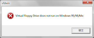
There are written "This is a virtual floppy drive for Windows NT / 2000 / XP / 2003 / Vista / Windows 7 (both 32-bit and 64-bit versions)" . But when launch it in Windows 7 64bit, it will show the following alert window.


I browse the bug tracker, and using google search.
There are many people had met this issue and not solve it yet.
But I am lucky that get one result can help me to solve this issue.

They provide patched source code and final binary.
Download the binary and overwrite the original file.
Try to launch it again and it is workable in Windows 7 64 bit.
But I am not checking it in 32 bit system.

The following link is original package and fixed package.
http://saren.twbbs.org/tools/v/VFD2.1%20x86.7z
http://saren.twbbs.org/tools/v/VFD2.1%20x86_64.7z

If it can't install, using Administrator to launch it.
If it can't start, stop WHQL when starting/rebooting Windows 7 and press F8 to disable WHQL.

Virtual Floppy Drive 2.1 for Windows 7 64 bit issue

Virtual Floppy Drive

這是一套在Windows下模擬磁碟機的虛擬驅動程式~
符合GNU/GPL Open Source的開放原始碼~

原始網頁上有註明「This is a virtual floppy drive for Windows NT / 2000 / XP / 2003 / Vista / Windows 7 (both 32-bit and 64-bit versions)」

而實際使用上若是在Windows 7 64bit下會秀出以下的錯誤訊息


搜尋VFD的Bug Tracker後確認不是個案
有一說法是在Windows 7 64bit下會發生 而32則是正常的

有幸搜尋到有人修改過原始碼 使得可以支援64bit

而在網頁上有提供修改過後的程式 只需要下載後覆蓋原始的檔案~
但是目前手邊沒有32bit的機器可以測試.

以下是包好的壓縮檔 有需要的可以自行下載
http://saren.twbbs.org/tools/v/VFD2.1%20x86.7z
http://saren.twbbs.org/tools/v/VFD2.1%20x86_64.7z

若是在Windows 7或Vista可能因為安全性而無法安裝
需先以系統管理者的權限啟動
同時Start時會因為WHQL認證而無法啟動
需重開機時按下F8停用WHQL認證